3D structures of individual mammalian genomes studied by single-cell Hi-C - PubMed Skip to main page content
U.S. flag

An official website of the United States government

Dot gov

The .gov means it’s official.
Federal government websites often end in .gov or .mil. Before sharing sensitive information, make sure you’re on a federal government site.

Https

The site is secure.
The https:// ensures that you are connecting to the official website and that any information you provide is encrypted and transmitted securely.

Access keys NCBI Homepage MyNCBI Homepage Main Content Main Navigation
. 2017 Apr 6;544(7648):59-64.
doi: 10.1038/nature21429. Epub 2017 Mar 13.

3D structures of individual mammalian genomes studied by single-cell Hi-C

Affiliations

3D structures of individual mammalian genomes studied by single-cell Hi-C

Tim J Stevens et al. Nature. .

Abstract

The folding of genomic DNA from the beads-on-a-string-like structure of nucleosomes into higher-order assemblies is crucially linked to nuclear processes. Here we calculate 3D structures of entire mammalian genomes using data from a new chromosome conformation capture procedure that allows us to first image and then process single cells. The technique enables genome folding to be examined at a scale of less than 100 kb, and chromosome structures to be validated. The structures of individual topological-associated domains and loops vary substantially from cell to cell. By contrast, A and B compartments, lamina-associated domains and active enhancers and promoters are organized in a consistent way on a genome-wide basis in every cell, suggesting that they could drive chromosome and genome folding. By studying genes regulated by pluripotency factor and nucleosome remodelling deacetylase (NuRD), we illustrate how the determination of single-cell genome structure provides a new approach for investigating biological processes.


Conflict of interest statement

The authors declare no competing interests.

Figures
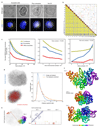
Extended Data Fig. 1
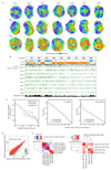
Extended Data Fig. 1. Quality control for Hi-C processing and 3D structure calculation.
a, Comparison of 3D images of CENP-A in haploid mES nuclei, expressing mEos3.2-tagged CENP-A and tandem iRFP-tagged histone H2B, with their corresponding white light images. b, Comparison of three single cell Hi-C contact maps (above the diagonal with contacts coloured red, yellow and blue), with the population Hi-C map (below the diagonal). c, An analysis of the accuracy and precision of the 100 kb structure calculation procedure for Cell 1. The graphs show how the global (dis)similarity of structures is affected by: the total number of contacts (left); the number of inter-chromosomal contacts (middle); and the number of random noise contacts (right). Mean RMSD values for all pairs of conformations ± the standard error of the mean are shown for: the precision within ensembles arising from ten re-calculations using the same contacts (red); the variation across ensembles arising from different random resampling (blue); and (as a measure of accuracy) the similarity to the best ensemble of structures (yellow). d, An example of a structure calculation carried out using either a single dataset, or after randomly merging 50% of the data from two different cells (lower). Strongly violated experimental restraints (>4 particle radii apart) are shown in red. The plot (right) shows the probability of any two particles connected by an experimental restraint being violated to different degrees. e, (left) The structure of chromosome 1 from Cell 6, where part of the chromosome lies at the opposite side of the genome structure, with no intermediate chromosome folding, illustrating the presence of a chromosomal break or recombination event. The contact map (right) shows that there are no contacts from the disconnected region to any other part of chromosome 1, but clear contacts to chromosomes 3 and 7. f, An example of an attempted calculation of the haploid genome structure for a cell containing a duplicated chromosome 2 shows many violations of the experimental restraints for that chromosome and a much more compacted structure (here compared with chromosomes 1 and 3). The structures are coloured according to position in the chromosome sequence from red through to purple (centromere to telomere).
Extended Data Fig. 2
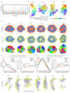
Extended Data Fig. 2. Validation and analysis of single cell contacts.
a, Structure of the entire haploid mESC genome from cells 2 to 8. The structural ensemble is represented by five superimposed conformations from repeat calculations, and is shown in three different orientations (after rotation through 90º relative to each other) with the chromosomes coloured according to their position in the chromosome sequence from red through to purple (centromere to telomere). b, Correspondence between the distribution of Hi-C contacts (both cis and trans), violations of the distance restraints in the 3D structures, and DNA replication timing for a representative chromosome (Chromosome 12). c, (left) Log scale plots of contact probability (Pcont) against sequence separation (S). The slopes for a power law relationship (Pcont ∝ Sα) where α is either -1.0 or -1.5 are also indicated. Data is shown for the combined single cell Hi-C contact data, for all of the non-sequential particles that are close to each other in the structures (<2 particle radii apart), and for the population Hi-C data. (right) The distribution in the number of intra- (cis) or inter-chromosomal (trans) contacts between 100 kb regions in the single-cell Hi-C data is shown for both the A and B compartments. d, Correlation of gene expression levels (left), and hierarchically clustered heat maps showing the pairwise enrichment of ChIP-seq peak overlaps between haploid and diploid mES cells (centre), and between Nanog ChIP-seq peak overlaps between haploid and diploid ES cells used in this study, as well as that previously published from diploid ES cells (right).
Extended Data Fig. 3
Extended Data Fig. 3. Chromosome interactions.
a, Violin plot showing the proportion of each chromosome that intermingles with other chromosomes. b, Pair-wise comparison of the chromosome structure in different cells by root mean square deviation (RMSD) analysis. Four models of chromosome 9 from a selection of different cells are shown, coloured according to the chromosome sequence (from red through to purple, centromere to telomere), together with a table showing the RMSD between the chromosomal 3D coordinates for each cell (bottom). c, Further cross-sections from cells 3-8 through the structures of haploid genomes (see Fig. 2e), coloured according to: (top) whether the sequence is in the A or B compartment; (centre) whether the sequence is part of a constitutive lamin-associated domain (cLAD) or contains highly expressed genes (coloured yellow and blue, respectively); and (bottom) identity of the chromosomes. In each case the figures show an ensemble of five superimposed conformations arising from repeat calculations using different randomly generated sets of coordinates. d, An analysis of the genome depth of various chromatin class categories, determined by k-means clustering of 100 kb segments according to the presence of histone H3 ChIP-seq data. The Active class is associated with H3K4me3, Polycomb with H3K27me3, Inactive with H3K9me3, and null the remainder. (left) The probability distribution for each of the categories at different normalized nucleus depths. (right) The divergence of the probability distribution for each category from the whole genome average. Data is shown for the genome structures of all cells. e, An analysis of the genome depth for regions with differing levels of gene expression, as measured by nuclear RNA-seq. Here RNA-seq signal peaks were ranked and split into five classes. As in panel d, the probability distribution for each class with regard to genome depth is shown (left), together with the divergence of each distribution from the genome as a whole (right). f, Further comparisons of the structure of chromosome 3 from different cells, coloured according to whether the sequence is part of the constitutive LAD domains (yellow), with the positions of highly expressed genes indicated by the presence of blue rings (larger circles indicate higher expression).
Extended Data Fig. 4
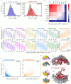
Extended Data Fig. 4. Relationship between genome folding and gene expression.
a, Calculation of 3D spatial clustering compared to a random hypothesis where the same data were circularly permuted around the sequence, and repeating the calculations, using the same structure. Two examples, showing strong (Klf4/H3K4me1) and weaker (Nanog/H3K27me3) spatial co-localisation, compared to random, are shown. b, The enrichment in spatial density (after removal of any clustering expected from their being located nearby in the same chromosome sequence), of histone H3 with various post-translational modifications and selected pluripotency factors as determined using ChIP-seq data. The enrichment is calculated over all cells as the Kullback-Liebler divergence of the normalized spatial density distribution from a random, circularly permuted, expectation (see Supplementary Methods for more details), and the data are presented in hierarchical order, grouping the most similar datasets together. c, Box and whisker plots showing enhancer, promoter and repetitive sequence content (lower row), and the enrichment in spatial density of different types of enhancer, promoter and repetitive sequence (upper row), after the data have been divided into ten groups based on increasing distance from the nearest inter-chromosomal interface. The whiskers represent the 10th and 90th percentiles, the boxes represent the range from the 25th to 75th percentile, and outliers are shown as dots. Mean and median values are shown with black crosses and bars, respectively. The R-values are the Pearson’s correlation coefficient on the underlying, unranked data. d, Plots of the level of gene expression as measured by the nuclear RNA-seq signal within 1 Mb regions against distance from the nearest inter-chromosomal interface (left) and the outer surface of the A compartment (right). e, Examples of inter-chromosomal interfaces from two different cells where the chromosomes are coloured increasingly brightly red for higher enrichment in the density of gene expression, compared to what would be expected for a given sequence separation. The remainder of the two chromosomes is coloured grey, and the positions of promoters are indicated by blue circles. The same views are shown with the two different chromosomes coloured yellow and blue (upper), or with their regions in the A and B compartments coloured blue and red (lower).
Extended Data Fig. 5
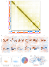
Extended Data Fig. 5. Chromosome folding into compartments, TADs and loops.
a, A contact map showing the population Hi-C data for chromosome 12 with TADs identified using the directionality index in blue. On the left hand side and below, data tracks are shown identifying the A and B compartments (in blue and red, respectively), and highly expressed genes (in magenta). b, Further comparisons (see Fig. 4b) showing the structures (and their variability) of two B compartment TADs either side of a highly expressed gene(s) in a short region of A compartment, or at a boundary between the A and B compartments (lower). Ensembles of five superimposed conformations, from repeat calculations using the same experimental data, are shown with pairs of TADs highlighted and coloured according to whether they are in the A or B compartments (blue and red, respectively), with white indicating a transitional segment (between A and B). TAD boundaries are marked by asterisks. c, Scatter plots of the mean radius of gyration for 1 Mb regions of genome structure compared to the average number of single-cell Hi-C contacts, within the same region, considering a 1 Mb sliding analysis window. Data is shown for all genome structures and split according to cis contacts (left) and trans contacts (right). d, Structure of Chromosome 12, with the A compartment coloured blue and positions of CTCF/Cohesin loops identified by Rao et al. (Ref. 7) indicated by dotted red lines. The pie chart shows the numbers of loops between sequences in the A and B compartments.
Extended Data Fig. 6
Extended Data Fig. 6. Chromosome folding into TADs.
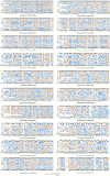
Bar charts of the mean radius of gyration (ROG) values of TADs identified using the directionality index for all the different chromosomes. The data are mean values over all structure conformations, scaled according to TAD size, and presented as quantile values for the chromosome. The 50th percentile value corresponds to the central grey line. Values below this are colored blue and above this are red. TADs that contain both regions of early replication timing (above 90th percentile) and moderate restraint violation (see Extended Data Fig. 2b) are excluded from the calculation. The errors in the ROG are the percentiles at ± the standard error of the mean. Values for multiple cells are presented in hierarchical cluster order, grouping the most similar cells together.
Extended Data Fig. 7
Extended Data Fig. 7. Chromosome folding into loops.
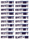
A genome-wide analysis illustrating whether CTCF/Cohesin loops could be formed in the different single cells, in each chromosome. A black square indicates that the two boundaries in the loop could interact, whilst a white square indicates that the two relevant particles are too far apart in the structure. The loop boundary separation, in particles, is shown along the x axis. The bar chart across the top shows the probability, for each loop, of random particles (pairs with the same sequence separation) forming the same number of contacts, or better. The probability of choosing a set of loop boundary points, which interact more frequently than we observed is 0.00072 (see Supplementary Methods).
Extended Data Fig. 8
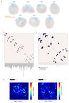
Extended Data Fig. 8. Understanding the nature of gene networks in mouse embryonic stem cells.
a, Structures of Cells 2-8 illustrating the interactions identified between the Nanog gene and other regions of the genome by population 4C (Ref. 34). Chromosome 6 is coloured in blue, with the position of the Nanog gene highlighted in yellow, whilst the remainder of the chromosomes are coloured grey. Interacting positions in the genome are indicated by red circles. b, Heat map showing the number of times a particular interaction is detected between two of the 4C Nanog-interacting points. c, Heat map showing the number of times a particular interaction is detected between two of the 4C Pou5f1-interacting points. In both b,c the interaction points are presented in hierarchical order grouping the regions that show the most interactions together. d, 2D single molecule tracking using photo-activated light microscopy (PALM) in live mESCs shows clustering of CHD4 and MBD3. In both cases, a heat map of a single cell is shown where the pixels have been colour-coded according to the density of molecules detected in that region.
Fig. 1
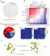
Fig. 1. Calculation of 3D genome structures from single cell Hi-C data.
a, Schematic of the protocol used to image and process single nuclei. b, Colour density matrices representing the relative number of contacts observed between different pairs of chromosomes. c, Five superimposed structures from a single cell, from repeat calculations using 100 kb particles and the same experimental data, with the chromosomes coloured differently. An expanded view of Chromosome 10 is shown, coloured from red through to purple (centromere to telomere), together with an illustration of the restraints determining its structure.
Fig. 2
Fig. 2. Large-scale structure of the genome.
a, Five superimposed structures from a single cell in three different orientations with the chromosomes coloured from red through to purple (centromere to telomere). b, Superposition of two single cell structures with images of mEos3.2-tagged CENP-A recorded from the same single cells. The centromeres from the images are shown as yellow spheres and the centromeric ends of the chromosomes are coloured red. The same structures after rotation through 90º are shown below. c, 3D structure of a haploid mES genome with expanded views of the separate chromosome territories (left), and the spatial distribution of the A (blue) and B (red) compartments (right). d, Structure of chromosome 9 from two different cells coloured (left) from red through to purple (centromere to telomere), or (right) according to whether the sequence is found in either the A (blue) or B (red) compartments. e, Cross-sections through five superimposed 3D structures from two different cells, coloured according to whether: (left) the sequence is in the A or B compartment; (centre) is part of a constitutive lamin-associated domain (cLAD) (yellow) or contains highly expressed genes (blue); and (right) chromosome identity. f, Structures of selected chromosomes from a single cell illustrating the different ways chromosomes can contribute to the A/B compartments. g, Chromosome 3 from a single cell with the positions of highly expressed genes shown as blue circles (larger circles indicate higher expression) and lamin associated regions shown in yellow (left), and where the sequence is coloured according to whether it is in the A or B compartment (right).
Fig. 3
Fig. 3. Relationship between genome folding and gene expression.
The enrichment in spatial density of: a, enhancers and promoters annotated using ChIP-seq data; b, gene expression determined from nuclear RNA-seq data, with genes separated according to their relative level of expression. In both (a) and (b) the data are presented in hierarchical order, grouping the most similar datasets together. c, The enrichment in the spatial density of gene expression vs distance from the nearest inter-chromosomal interface (left) and the outer surface of the A compartment (right). d, Median vs standard deviation of the depth from the nuclear periphery for particles in the A (blue) or B (red) compartments. Particles containing pluripotency genes are indicated by yellow circles – the sizes illustrate relative levels of expression. e, Comparison of nuclear depth in either the 3D structures (n=8) or DNA-FISH analysis of the Nanog (n=84 cells) and Zfp42 (n=142 cells) genes, with Pou5f1 (n=189 cells) as a control. Gm27037 (n=16 cells), a pseudo-gene, provided a non-pluripotency factor control.
Fig. 4
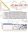
Fig. 4. Structure of topological-associated domains (TADs) and CTCF/Cohesin loops.
a, Part of the Hi-C contact map from Chromosome 12 showing: (above the diagonal) contacts observed in three different single cells (coloured red, yellow and blue); (below the diagonal) the corresponding population Hi-C data. TADs identified by Dixon et al. (Ref. 5) are shown in dark blue, and the two regions analysed in panel b are shown in magenta. b, Ensembles of five superimposed structures showing: (left) two B compartment TADs (Region 1 in a); (right) TADs either side of an A/B compartment boundary (Region 2 in a). The TADs are coloured according to whether they are in the A (blue) or B (red) compartments, with white indicating a transitional segment (between A and B). Boundaries are marked by asterisks. c, The mean radius of gyration (ROG) of Chromosome 12 TADs ± the standard error of the mean. The data are scaled according to TAD size, and presented as quantile values for the chromosome. Values below the 50th percentile value are colored blue and above it red. The ROG values for multiple cells are presented in hierarchical cluster order, grouping the most similar cell traces together. A schematic illustrating the calculation of the ROG as a measure of the compaction of a particle chain is shown below. d, Analysis illustrating whether CTCF/Cohesin loops with sequence separation >600 kb identified by Rao, et al. (Ref. 7) could be formed in the different single cells. A black square indicates that a loop could be formed, whilst a white square indicates that the two relevant particles are too far apart in the structure. The bar chart across the top shows the probability, for each loop, of random particles (pairs with the same sequence separation) forming the same number of contacts, or better.
Fig. 5
Fig. 5. Understanding the nature of gene networks in mouse ESCs.
a, Structure of an individual cell illustrating the interactions identified between the Nanog gene in Chromosome 6 (coloured yellow and blue, respectively) and other regions of the genome (red circles) in a population 4C experiment. b, The spatial density enrichment of NuRD components (CHD4 and MBD3), pluripotency factors and NuRD regulated genes, as well as annotated enhancers and promoters defined using ChIP-seq data. c, Pie chart showing the numbers of NuRD regulated genes in different classes. d, A heat map showing clustering of CHD4 and MBD3 molecules in 2D super-resolution PALM in fixed mESCs. e, Structures of a region of chromosome 16 in two different cells, showing clustering of regions containing genes that are highly regulated by NuRD (highlighted in yellow). The positions of genes in either the CHD4-knockdown or MBD3-null cells that are down-regulated (red circles) or up-regulated (blue circles) are indicated by circles (larger for more highly regulated).

Comment in

Similar articles

Cited by

References

    1. Cremer T, et al. The 4D nucleome: Evidence for a dynamic nuclear landscape based on co-aligned active and inactive nuclear compartments. FEBS Lett. 2015;589:2931–2943. doi: 10.1016/j.febslet.2015.05.037. - DOI - PubMed
    1. Bickmore WA, van Steensel B. Genome architecture: domain organization of interphase chromosomes. Cell. 2013;152:1270–1284. doi: 10.1016/j.cell.2013.02.001. - DOI - PubMed
    1. Lieberman-Aiden E, et al. Comprehensive mapping of long-range interactions reveals folding principles of the human genome. Science. 2009;326:289–293. doi: 10.1126/science.1181369. - DOI - PMC - PubMed
    1. Nora EP, et al. Spatial partitioning of the regulatory landscape of the X-inactivation centre. Nature. 2012;485:381–385. doi: 10.1038/nature11049. - DOI - PMC - PubMed
    1. Dixon JR, et al. Topological domains in mammalian genomes identified by analysis of chromatin interactions. Nature. 2012;485:376–380. doi: 10.1038/nature11082. - DOI - PMC - PubMed

Publication types

MeSH terms