3D Imaging of Water-Drop Condensation on Hydrophobic and Hydrophilic Lubricant-Impregnated Surfaces
- PMID: 27040483
- PMCID: PMC4819200
- DOI: 10.1038/srep23687
3D Imaging of Water-Drop Condensation on Hydrophobic and Hydrophilic Lubricant-Impregnated Surfaces
Abstract
Condensation of water from the atmosphere on a solid surface is an ubiquitous phenomenon in nature and has diverse technological applications, e.g. in heat and mass transfer. We investigated the condensation kinetics of water drops on a lubricant-impregnated surface, i.e., a micropillar array impregnated with a non-volatile ionic liquid. Growing and coalescing drops were imaged in 3D using a laser scanning confocal microscope equipped with a temperature and humidity control. Different stages of condensation can be discriminated. On a lubricant-impregnated hydrophobic micropillar array these are: (1) Nucleation on the lubricant surface. (2) Regular alignment of water drops between micropillars and formation of a three-phase contact line on a bottom of the substrate. (3) Deformation and bridging by coalescence which eventually leads to a detachment of the drops from the bottom substrate. The drop-substrate contact does not result in breakdown of the slippery behaviour. Contrary, on a lubricant-impregnated hydrophilic micropillar array, the condensed water drops replace the lubricant. Consequently, the surface loses its slippery property. Our results demonstrate that a Wenzel-like to Cassie transition, required to maintain the facile removal of condensed water drops, can be induced by well-chosen surface hydrophobicity.
Figures


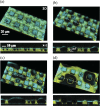
 and φa are measured at a height of the pillar’s top face (z = 10 μm). The pillars had a rectangular or circular cross-section of 10 μm or 20 μm width and identical spacing.


Similar articles
-
Direct observation of drops on slippery lubricant-infused surfaces.Soft Matter. 2015 Oct 14;11(38):7617-26. doi: 10.1039/c5sm01809a. Soft Matter. 2015. PMID: 26291621
-
Surfactant solutions and porous substrates: spreading and imbibition.Adv Colloid Interface Sci. 2004 Nov 29;111(1-2):3-27. doi: 10.1016/j.cis.2004.07.007. Adv Colloid Interface Sci. 2004. PMID: 15571660
-
Design and Fabrication of a Hybrid Superhydrophobic-Hydrophilic Surface That Exhibits Stable Dropwise Condensation.ACS Appl Mater Interfaces. 2015 Oct 28;7(42):23575-88. doi: 10.1021/acsami.5b06759. Epub 2015 Oct 19. ACS Appl Mater Interfaces. 2015. PMID: 26372672
-
The challenge of lubricant-replenishment on lubricant-impregnated surfaces.Adv Colloid Interface Sci. 2021 Jan;287:102329. doi: 10.1016/j.cis.2020.102329. Epub 2020 Nov 26. Adv Colloid Interface Sci. 2021. PMID: 33302056 Review.
-
Hydrophilic and Hydrophobic Surfaces: Features of Interaction with Liquid Drops.Materials (Basel). 2023 Aug 30;16(17):5932. doi: 10.3390/ma16175932. Materials (Basel). 2023. PMID: 37687631 Free PMC article. Review.
Cited by
-
A Water Droplet Pinning and Heat Transfer Characteristics on an Inclined Hydrophobic Surface.Sci Rep. 2018 Feb 15;8(1):3061. doi: 10.1038/s41598-018-21511-w. Sci Rep. 2018. PMID: 29449624 Free PMC article.
-
How Frost Forms and Grows on Lubricated Micro- and Nanostructured Surfaces.ACS Nano. 2021 Mar 23;15(3):4658-4668. doi: 10.1021/acsnano.0c09152. Epub 2021 Mar 1. ACS Nano. 2021. PMID: 33647197 Free PMC article.
-
Quantitative surface free energy with micro-colloid probe pairs.RSC Adv. 2023 Jan 18;13(4):2718-2726. doi: 10.1039/d2ra05508b. eCollection 2023 Jan 11. RSC Adv. 2023. PMID: 36741155 Free PMC article.
-
Effects and Mechanism of Surface Water Wettability and Operating Frequency on Response Linearity of Flexible IDE Capacitive Humidity Sensor.Sensors (Basel). 2021 Oct 6;21(19):6633. doi: 10.3390/s21196633. Sensors (Basel). 2021. PMID: 34640953 Free PMC article.
-
Capillary Balancing: Designing Frost-Resistant Lubricant-Infused Surfaces.Nano Lett. 2020 Dec 9;20(12):8508-8515. doi: 10.1021/acs.nanolett.0c02956. Epub 2020 Nov 18. Nano Lett. 2020. PMID: 33206541 Free PMC article.
References
-
- Beer J. M. High Efficiency Electric Power Generation: The Environmental Role. Prog. Energy Combust. Sci. 33, 107–134 (2012).
-
- Udell K. S. Heat Transfer in Porous Media Considering Phase Change and Capillarity – The heat pipe effect. Int. J. Heat Mass Transfer 28, 485–495 (1985).
-
- Parker A. R. & Lawrence C. R. Water Capture by a Desert Beetle. Nature 414, 33–34 (2001). - PubMed
-
- Zhai L. et al.. Patterned Superhydrophobic Surfaces: Toward a Synthetic Mimic of the Namib Desert Beetle. Nano Lett. 6, 1213–1217 (2006). - PubMed
-
- Park K. C., Chhatre S. S., Srinivasan S., Cohen R. E. & McKinley G. H. Optimal Design of Permeable Fiber Network Structures for Fog Harvesting. Langmuir 29, 13269–13277 (2013). - PubMed
Publication types
LinkOut - more resources
Full Text Sources
Other Literature Sources

