Direct transfer of magnetic sensor devices to elastomeric supports for stretchable electronics
- PMID: 25639256
- PMCID: PMC5093710
- DOI: 10.1002/adma.201403998
Direct transfer of magnetic sensor devices to elastomeric supports for stretchable electronics
Abstract
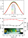
A novel fabrication method for stretchable magnetoresistive sensors is introduced, which allows the transfer of a complex microsensor systems prepared on common rigid donor substrates to prestretched elastomeric membranes in a single step. This direct transfer printing method boosts the fabrication potential of stretchable magnetoelectronics in terms of miniaturization and level of complexity, and provides strain-invariant sensors up to 30% tensile deformation.
Keywords: giant magnetoresistive multilayers; giant magnetoresistive sensors; stretchable electronics; stretchable magnetoelectronics; transfer printing.
© 2015 The Authors. Published by WILEY-VCH Verlag GmbH & Co. KGaA, Weinheim.
Figures


Similar articles
-
Printable and Stretchable Giant Magnetoresistive Sensors for Highly Compliant and Skin-Conformal Electronics.Adv Mater. 2021 Mar;33(12):e2005521. doi: 10.1002/adma.202005521. Epub 2021 Feb 2. Adv Mater. 2021. PMID: 33533129 Free PMC article.
-
Rubbery Electronics Fully Made of Stretchable Elastomeric Electronic Materials.Adv Mater. 2020 Apr;32(15):e1902417. doi: 10.1002/adma.201902417. Epub 2019 Jun 17. Adv Mater. 2020. PMID: 31206819 Review.
-
High-Resolution Rapid Prototyping of Liquid Metal Electronics by Direct Writing on Highly Prestretched Substrates.ACS Omega. 2019 Dec 5;4(25):21072-21077. doi: 10.1021/acsomega.9b02440. eCollection 2019 Dec 17. ACS Omega. 2019. PMID: 31867499 Free PMC article.
-
Omnidirectional Printing of Soft Elastomer for Liquid-State Stretchable Electronics.ACS Appl Mater Interfaces. 2019 May 22;11(20):18590-18598. doi: 10.1021/acsami.9b04730. Epub 2019 May 13. ACS Appl Mater Interfaces. 2019. PMID: 31050403
-
Stretchable, Skin-Attachable Electronics with Integrated Energy Storage Devices for Biosignal Monitoring.Acc Chem Res. 2019 Jan 15;52(1):91-99. doi: 10.1021/acs.accounts.8b00508. Epub 2018 Dec 26. Acc Chem Res. 2019. PMID: 30586283 Review.
Cited by
-
Multilevel design and construction in nanomembrane rolling for three-dimensional angle-sensitive photodetection.Nat Commun. 2024 Apr 9;15(1):3066. doi: 10.1038/s41467-024-47405-2. Nat Commun. 2024. PMID: 38594254 Free PMC article.
-
Scalable Microfabrication Procedures for Adhesive-Integrated Flexible and Stretchable Electronic Sensors.Sensors (Basel). 2015 Sep 16;15(9):23459-76. doi: 10.3390/s150923459. Sensors (Basel). 2015. PMID: 26389915 Free PMC article.
-
High Performance MgO-barrier Magnetic Tunnel Junctions for Flexible and Wearable Spintronic Applications.Sci Rep. 2017 Feb 2;7:42001. doi: 10.1038/srep42001. Sci Rep. 2017. PMID: 28150807 Free PMC article.
-
Transfer Printing and its Applications in Flexible Electronic Devices.Nanomaterials (Basel). 2019 Feb 18;9(2):283. doi: 10.3390/nano9020283. Nanomaterials (Basel). 2019. PMID: 30781651 Free PMC article.
-
An ultrathin, rapidly fabricated, flexible giant magnetoresistive electronic skin.Microsyst Nanoeng. 2024 Aug 12;10:109. doi: 10.1038/s41378-024-00716-2. eCollection 2024. Microsyst Nanoeng. 2024. PMID: 39139649 Free PMC article.
References
-
- Rogers J. A., Someya T., Huang Y. G., Science 2010, 327, 1603. - PubMed
-
- Wagner S., Bauer S., MRS Bull. 2012, 37, 207.
-
- Kim D. H., Lu N. S., Ma R., Kim Y. S., Kim R. H., Wang S. D., Wu J., Won S. M., Tao H., Islam A., Yu K. J., Kim T. I., Chowdhury R., Ying M., Xu L. Z., Li M., Chung H. J., Keum H., McCormick M., Liu P., Zhang Y. W., Omenetto F. G., Huang Y. G., Coleman T., Rogers J. A., Science 2011, 333, 838. - PubMed
LinkOut - more resources
Full Text Sources
Other Literature Sources

